

picoComputer is a computer architecture developed by Dr Jozo Dujmović in 1989 to aid teaching of assembly languages. Along with the architecture design, Dr Dujmović developed a DOS application called “pC Assembler and Simulator”, or pCAS for short.
Being written more than twenty years ago, pCAS is very outdated. Although, it can still run on 32-bit Windows operating systems and under DOS emulators like DOSBox, it is not the most convenient way to write applications today. You can download a copy of pCAS from the Download page.
The pC architecture itself, however, is still relevant today. It was never meant to be able to compete with the current platforms, but rather to provide a framework for demonstrating low-level programming. Combined with the Messy Lab IDE, much of the unnecessary frustration is avoided.
It is worth noting that the basic principles of the computer technology didn’t change much, if at all, since its inception. Sure enough, speeds increased, number of used components sky-rocketed, various optimizations were applied on many levels, different instruction sets and accompanying philosophies were developed and then abandoned, but the most basic principles that the picoComputer architecture is capable of demonstrating, remained.
This page does into details of the picoComputer arhitecture and its instruction set, as well as the syntax used to write pC programs.
Table of content:
Architecture
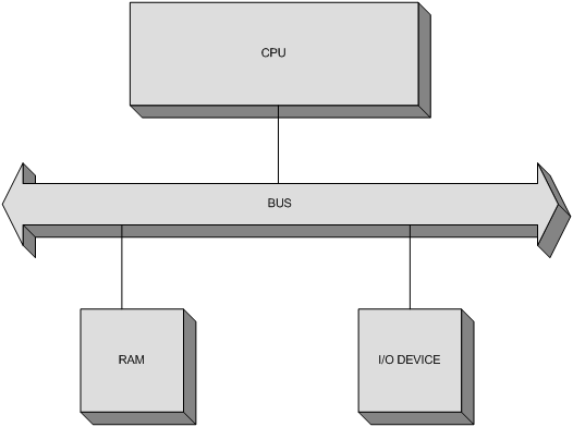
picoComputer features a very simple architecture that consists of the CPU, RAM and an I/O Device, connected using a single Bus, as shown on the following figure:
Memory
The memory of a picoComputer contains a maximum of 65536 words, each 16 bits wide. That means that the addresses are 16 bits wide as well. The memory is divided in two logical parts, as depicted on the following figure:
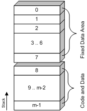
The Fixed Data Area consists of the first 8 memory locations and these locations play the role similar to that of the general-purpose processor Registers found in most of the other processor architectures.
The rest of the memory can be used arbitrarily, but it is important to keep in mind that the call stack starts at the last memory location (the one with the highest address) and grows downward. That’s why it is important not to use the memory locations that could be overwritten by the stack as it grows.
I/O Device
The I/O Device is basically a screen and a keyboard in the same case. That way the numerical data can be entered using the keyboard, and the screen can display the values from the picoComputer memory.
As you can see, the design is as simple as possible, which follows the general philosophy of the platform. The input/output operations are blocking calls, which means that there is no parallelism. Consequently, it is not necessary to keep polling a status register (which does not even exist) to check whether an I/O operation is complete. By the time the instruction is executed, so is the I/O operation.
It is worth noting that there is no way to handle interrupts on the picoComputer. The only interrupt that the I/O Device can generate is the one signaling an invalid input. Each interrupt simply aborts the program execution on the picoComputer.
Processor
The processor has two accessible registers, PC and SP. The PC register (Program Counter) points to the current instruction in memory. The SP register is the Stack Pointer. Neither one is can be used in an instruction as an operand.
The value of PC is incremented automatically after every executed instruction, or it can be directly set by a branch instruction. It is assumed that there is a way to initialize PC before the program execution starts. The same applies to the initial content of the memory.
The value of the SP register is updated when executing one of the two instructions used to support sub-routines and that is the only supported way to use the stack. Of course, since the stack is located in RAM like any other data, it can be modified manually, but that is simply not its recommended use.
There is a number of internal registers, but the internal workings of a processor are generally not of any consequence when writing an assembly program. That is why, they fall out of the scope of this article.
Syntax
Consider the following picoComputer program:
; Symbols
        a = 1
        b = 2
        c = 3

        ; Origin
        ORG 8

        ; Instructions

start:  in a                ; input a
        in b                ; input b
        add c, a, b         ; c = a + b
        out c               ; output c

        in a                ; input a
        beq a, 0, end       ; if a=0 goto end
        beq a, a, start     ; goto start
end:    stop                ; stop execution
Every pC program consists of three sections. The first one contains the Symbol definitions, the second one contains a single ORG directive which specifies the address of the first instruction and the third one contains a list of instructions of the program.
Symbols
The Symbols section is used to define symbol names and their values. Using symbols allows the code to be more human-readable, however the symbol names are discarded during the assembling process, and only their numerical values are used.
Another way to define symbols is by defining labels. A label is an identifier put in front of an instruction followed by a colon. Examples are start and end from the code above. The value of a label is the address of the instruction following it. For example, label start has the value of 8.
Origin
The ORG directive is used to define the address of the first instruction. This is the value that will be stored in the PC register of the processor when loading the program.
Instructions
An instruction is defined by its symbolic name, followed by a comma-separated list of operands. There are four kinds of operands supported in the pC symbolic language, as explained in the following table:
| Format | Example | Addressing | Description |
|---|---|---|---|
| symbol | a | Direct | The Address of the memory location holding the operand is the value of the symbol. |
| (symbol) | (a) | Indirect | The Address of the memory location holding the operand is stored in memory. The address of the location holding the address is the value of the symbol. |
| #symbol | #a | Immidiate | The operand value is the value of the symbol. |
| constant | 5 | Immidiate | The operand value is the specified constant itself. |
The following section provides the detailed explanation of the available instructions.
Instruction set
picoComputer features a 3-operand instruction set. That means that an instruction can have a maximum of 3 operands. An instruction is either one or two words long depending on whether it contains a constant (which occupies the second word).
The following figure shows the format of a typical pC instruction:
| OP Code | i1 | a1 | i2 | a2 | i3 | a3 | |||||||||
|---|---|---|---|---|---|---|---|---|---|---|---|---|---|---|---|
| 15 | 14 | 13 | 12 | 11 | 10 | 9 | 8 | 7 | 6 | 5 | 4 | 3 | 2 | 1 | 0 |
The bits 12 through 15 represent the Operation Code, while the rest is used to encode the three operands. The first operand is encoded by bits in i1 and a1 fields.
Since the OP Code is encoded in 4 bits, it is obvious that the pC has a maximum of 16 different instructions.
Each operand is encoded using the 1-bit value i and the 3-bit value a. The value i indicates whether the addressing is indirect or direct (encoded as 1 and 0, respectively), and the value a represents the address in RAM. Because a is 3 bits wide, it can only point to locations 0 through 7 and that is the part of memory designated as the Fixed Data Area (FDA).
Accessing other parts of memory is achieved by using the indirect addressing. The address of the desired location is stored within the FDA. The value a points to the location in the FDA that holds the address and i is set to 1 to indicate the indirect addressing.
Certain instructions follow the above described format only partially and might use some bits reserved for an operand as an extension of its OP Code.
Move
The Move instructions are the most basic and the most commonly executed instructions. Generally, their purpose is to copy data from one place to the other. picoComputer has only one such instruction.
| OP Code | Symbolic name | |
|---|---|---|
| Move | 0000 | MOV |
Depending on the operands, there are four types of the MOV instruction.
Type 1
MOV x, y| OP Code | i1 | a1 | i2 | a2 | i3 | a3 | |||||||||
|---|---|---|---|---|---|---|---|---|---|---|---|---|---|---|---|
| 0 |
0 |
0 |
0 |
x |
x | x |
x |
y |
y |
y |
y |
0 |
0 |
0 |
0 |
If i3 equals 0 and a3 equals 0, the value of y is stored in x, i.e. the value of the second argument is stored in the first.
Type 2
MOV x, 5
MOV (x), #c| OP Code | i1 | a1 | i2 | a2 | i3 | a3 | |||||||||
|---|---|---|---|---|---|---|---|---|---|---|---|---|---|---|---|
| 0 |
0 |
0 |
0 |
x |
x |
x |
x |
? |
? |
? |
? |
1 |
0 |
0 |
0 |
| c | c | c | c | c | c | c | c | c | c | c | c | c | c | c | c |
If i3 equals 1 and a3 equals 0, the constant c from the second word of the instruction is stored in x, i.e. the memory location addressed by the first argument.
Type 3
MOV x, y, #n
MOV (x), (y), 5| OP Code | i1 | a1 | i2 | a2 | i3 | a3 | |||||||||
|---|---|---|---|---|---|---|---|---|---|---|---|---|---|---|---|
| 0 |
0 |
0 |
0 |
x |
x |
x |
x |
y |
y |
y |
y |
1 |
1 |
1 |
1 |
| n | n | n | n | n | n | n | n | n | n | n | n | n | n | n | n |
If i3 equals 1 and a3 equals 7 (binary 111), the array starting at the location y is stored starting with the location x. The length of the array, n is stored in the second word of the instruction.
Type 4
MOV x, y| OP Code | i1 | a1 | i2 | a2 | i3 | a3 | |||||||||
|---|---|---|---|---|---|---|---|---|---|---|---|---|---|---|---|
| 0 |
0 |
0 |
0 |
x |
x | x |
x |
y |
y |
y |
y |
0 |
n |
n |
n |
If i3 equals 0 and a3 is greater than 0, the array starting at the location y is stored starting with the location x. The length of the array is stored in the memory location from a3. Obviously, the address cannot be 0, because the instruction would get a different meaning (it would be formatted as Type 1).
Arithmetic
The Arithmetic instructions perform the basic calculations. picoComputer supports Addition, Subtraction, Multiplication and Division. Each operation is supported by two machine instructions, sharing the same symbolic name.
The difference between the two is whether an operand is a constant value or not.
| OP Code | Symbolic name | ||
|---|---|---|---|
| Addition | 0001 | 1001 | ADD |
| Subtraction | 0010 | 1010 | SUB |
| Multiplication | 0011 | 1011 | MUL |
| Division | 0100 | 1100 | DIV |
| With Constant | Without Constant | ||
Without Constant
When none of the operands are constants, arithmetic instructions have the following format:
ADD x, y, z
SUB (x), y, z
MUL x, (y), (z)
DIV (x), (y), z| OP Code | i1 | a1 | i2 | a2 | i3 | a3 | |||||||||
|---|---|---|---|---|---|---|---|---|---|---|---|---|---|---|---|
| 0 |
op |
op |
op |
x |
x | x |
x |
y |
y |
y |
y |
z |
z |
z |
z |
The result of the arithmetic operation specified by the op bits, performed between the operands y and z is stored in the memory location x.
With Constant
The arithmetic instructions can have one constant operand - either the second, or the third one. (The first one cannot be a constant because it is the destination. In C terminology, the first operand has to be an lvalue.)
The constant operand is marked in the first instruction word by setting the value of both i and a fields to zero.
When the Second operand is a constant, the instruction has the following format:
ADD x, 5, z
SUB (x), #c, z| OP Code | i1 | a1 | i2 | a2 | i3 | a3 | |||||||||
|---|---|---|---|---|---|---|---|---|---|---|---|---|---|---|---|
| 0 |
op |
op |
op |
x |
x | x |
x |
0 |
0 |
0 |
0 |
z |
z |
z |
z |
| c | c | c | c | c | c | c | c | c | c | c | c | c | c | c | c |
The result of the arithmetic operation between c and z is stored in x.
When the Third operand is a constant, the following format is used:
MUL x, y, 5
DIV (x), y, #c| OP Code | i1 | a1 | i2 | a2 | i3 | a3 | |||||||||
|---|---|---|---|---|---|---|---|---|---|---|---|---|---|---|---|
| 0 |
op |
op |
op |
x |
x | x |
x |
y |
y |
y |
y |
0 |
0 |
0 |
0 |
| c | c | c | c | c | c | c | c | c | c | c | c | c | c | c | c |
The result of the arithmetic operation between y and c is stored in x.
Note: Because zero is used to mark the constant operand, addressing memory location 0 is not allowed.
Branch
Branch instructions are used to control the execution flow of the program. Essentially, they alter the value of the PC (program counter) processor register if certain condition is met. Thus, the program can continue executing in two directions, hence the name branch. These instructions are also known as Jump instructions.
picoComputer has two branch instructions.
| OP Code | Symbolic name | |
|---|---|---|
| Branch If Equal | 0101 | BEQ |
| Branch If Greater | 0110 | BGT |
There are two formats of branch instructions, depending on the way the destination address is specified.
When the address is specified in the second word of the instruction, the following format is used:
BEQ x, y, is_eq
BGT (x), (y), is_gt| OP Code | i1 | a1 | i2 | a2 | i3 | a3 | |||||||||
|---|---|---|---|---|---|---|---|---|---|---|---|---|---|---|---|
| op |
op |
op |
op |
x |
x |
x |
x |
y |
y |
y |
y |
1 |
0 |
0 |
0 |
| c | c | c | c | c | c | c | c | c | c | c | c | c | c | c | c |
When i3 equals 1, and a3 equals 0, c is the the destination address.
Please note that is_eq and is_gt from the example are actually labels defined in front of the destination instructions.
When the address is specified in a memory location from the Fixed Data Area, the following format is used:
BEQ x, (y), (a)
BGT (x), y, (a)| OP Code | i1 | a1 | i2 | a2 | i3 | a3 | |||||||||
|---|---|---|---|---|---|---|---|---|---|---|---|---|---|---|---|
| op |
op |
op |
op |
x |
x |
x |
x |
y |
y |
y |
y |
0 |
a |
a |
a |
When i3 equals 0, a3 is the address of the memory location within the FDA that holds the destination address of the jump.
Operands x and y that are being compared in both of the formats are encoded as usual - with one exception! If both i and a fields equal 0, the operand is not the content of the memory location at address 0, but the constant 0. It is the only allowed constant in branch instructions.
The following example checks whether x equals 0:
BEQ x, 0, is_zeroI/O
There are two basic ways to handle communication with the Input/Output Devices. Either memory mapping is used, or there are special instructions used for the I/O.
If memory mapping is used, certain memory addresses are assigned to I/O Devices and the communication is achieved using the normal memory access instructions.
If dedicated I/O instructions are used, I/O Devices are accessed using an independent addressing system. picoComputer uses this approach, however, since it supports only a single device, there is no need for addresses at all.
| OP Code | Symbolic name | |
|---|---|---|
| Input |
0111 | IN |
| Output | 1000 | OUT |
The I/O instructions take two operands.
The first one is the destination, or the source, depending on whether the operation is input or output.
The second one is the length of the array to be transferred. It can be omitted when writing programs, and if that is the case, the default value (1) is used.
Depending on how the array length is stored, there are two formats of the instruction.
If the array length is stored in memory, the following format is used:
IN x, (n)
OUT (x), n| OP Code | i1 | a1 | i2 | a2 | i3 | a3 | |||||||||
|---|---|---|---|---|---|---|---|---|---|---|---|---|---|---|---|
| op |
op |
op |
op |
x |
x |
x |
x |
1 |
0 |
0 |
0 |
n |
n |
n |
n |
When i2 equals 1 and a2 equals 0, the length is in the memory location n.
If the length is stored as a constant within the instruction, the following format is used:
IN x, 5
OUT (x), #c| OP Code | i1 | a1 | i2 | a2 | i3 | a3 | |||||||||
|---|---|---|---|---|---|---|---|---|---|---|---|---|---|---|---|
| op |
op |
op |
op |
x |
x |
x |
x |
0 |
c |
c |
c |
c |
c |
c |
c |
When i2 equals 0, a2, i3 and a3 are used to store the array length.
Unlike other instructions that feature constants (immidiate operands), I/O instructions do not use a second word. Instead, the lowest 7 bits are used. That’s why c cannot be greater than 127.
Subroutine
Unlike Branch instructions, subroutine instructions provide a way to return to the address from which the jump was made, by storing the address on the Call Stack. Each use modifies the SP (Stack Pointer) register of the processor.
picoComputer provides two subroutine instructions - one for calling a subroutine, and one for returning from it.
| OP Code | Symbolic name | |
|---|---|---|
| Jump to Subroutine |
1101 | JSR |
| Return from Subroutine |
1110 | RTS |
The format of the JSR instruction is as follows:
JSR sub| OP Code | i1 | a1 | i2 | a2 | i3 | a3 | |||||||||
|---|---|---|---|---|---|---|---|---|---|---|---|---|---|---|---|
| 1 |
1 |
0 |
1 |
? |
? |
? |
? |
? |
? |
? |
? |
? |
? |
? |
? |
| c | c | c | c | c | c | c | c | c | c | c | c | c | c | c | c |
The jump destination address, c is stored in the second word.
In the example, sub is a label.
The RTS instruction is even simpler:
RTS| OP Code | i1 | a1 | i2 | a2 | i3 | a3 | |||||||||
|---|---|---|---|---|---|---|---|---|---|---|---|---|---|---|---|
| 1 |
1 |
1 |
0 |
? |
? |
? |
? |
? |
? |
? |
? |
? |
? |
? |
? |
The instruction takes no arguments.
In both instructions operand fields of the first word are unused and undefined.
Stop
The Stop instruction terminates the program execution. Additionally, the instruction can be used to send up to three values to the I/O Device.
| OP Code | Symbolic name | |
|---|---|---|
| Stop | 1111 | STOP |
The instruction uses the following format:
STOP
STOP x
STOP x, (y)
STOP (x), y, (z)| OP Code | i1 | a1 | i2 | a2 | i3 | a3 | |||||||||
|---|---|---|---|---|---|---|---|---|---|---|---|---|---|---|---|
| 1 |
1 |
1 |
1 |
x |
x | x |
x |
y |
y |
y |
y |
z |
z |
z |
z |
If x, y or z do not equal 0, the corresponding memory locations will be sent to the I/O Device. Consequently, memory location 0 cannot be displayed using this instruction.